Skills: PCB Design, Component Specification, ESD, EMI, USB Protocol
While I was interning, I fell into the rabbit hole of mechanical keyboards. I learned to lube switches and replaced my keycaps, but that wasn't enough. I wanted to use my design skills to create a completely custom mechanical keyboard. This project let me dip my feet into PCB design and ordering, as well as USB interface control, and basic ESD and EMI protections.
Of course, there's no point in designing something that already exists, or that solves no problem. I created a list of everything that annoyed me about my current computer interface interactions and decided to focus on one thing. In my work, I constantly had to put down my mouse to interact with my numpad. No matter how many hotkeys I memorized in various software, I always needed the mouse, and I always needed to input numbers. To address this, I decided to move the numpad to the left side of the keyboard (weird, I know) and compact the keyboard as much as possible without losing out on any valuable keys for macros and shortcuts.
Now, I'm not claiming that either of these things are new. '96%' Keyboards exist, which are essentially full-size keyboards that remove all unnecessary space, and 'Southpaw' keyboards move the numpad to the left side. However, both of these types of keyboards are highly unpopular/uncommon alone, and don't exist for purchase in combination. My combination would be useful to me and addresses an unmet need in the space.
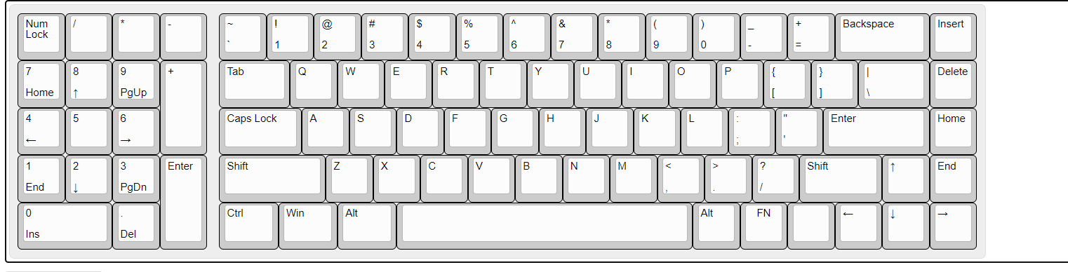
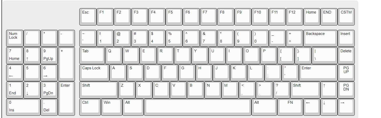
The first step I took was to play around with keymaps, looking at what I could do with the spacing and key layouts. I settled on three possible layouts, each slightly different, and printed them out to test the feel of the keyboard in a low-fidelity prototype.
I ended up settling on the annotated layout, because I wanted to make it easy to identify keys without looking at them, which the spaced function row does, and also to leave space in the top right to surface mount my microcontroller.


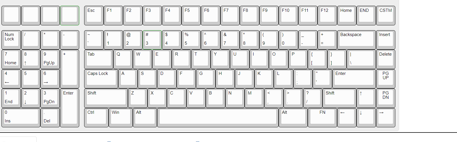
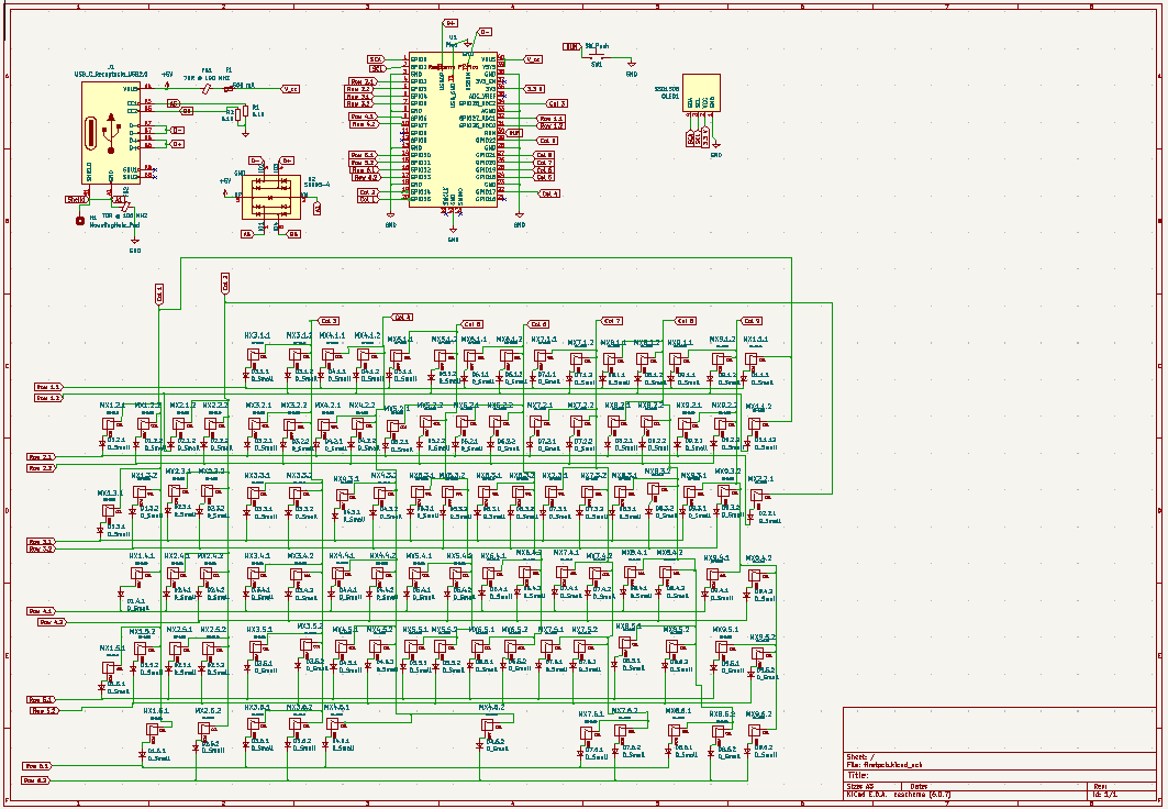
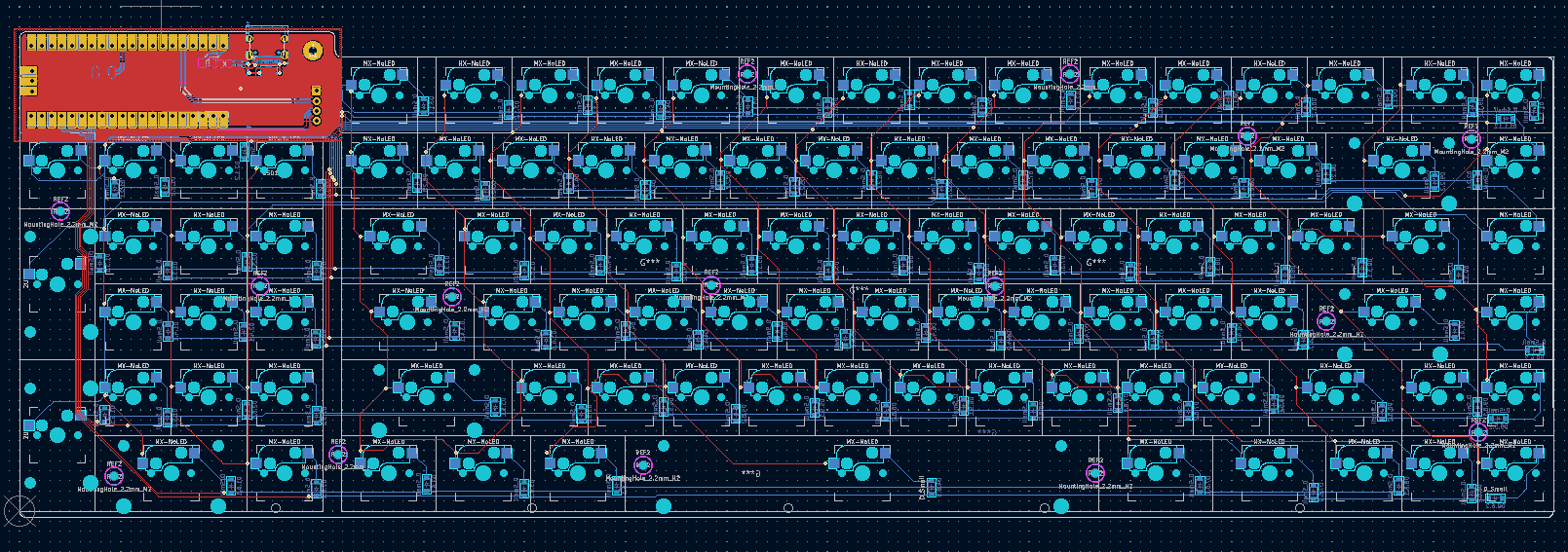
The annotations on the previous image helped me create duplex matrix for wiring each key, reducing noise and 'ghost' strokes. After creating the matrix, I created the schematic for my USB port and microcontroller.
After that, I designed the PCB using sound routing techniques and got some advice from EEs at my internship to inform my ESD and EMI suppression techniques. Everything is routed fairly optimally to reduce the space on the board and support a surface mounted Raspberry Pi Pico as the brains of the operation. This allows the board to be easily assembleable and repairable (and the brain only costs 4$!).
My project for this semester is to get ProjX MIT funding for the PCB purchasing, and design/machine a full aluminum case while I still work in a free machine shop here.
I'll keep you updated ;)