Skills: Design Optimization, FEA, Surface Modeling, CAD, Presentation, Project Management, Technical Feedback

The main point of my project was to make use of the Base Thickness feature in Inspire.
This tool was commonly asked about, covered by little documentation, and definitely underutilized by Altair clients.
In particular, Honeywell and Northrop Grumman were interested in learning more about this feature. It's a very powerful tool for surface models, which are very common in the aerospace industry.
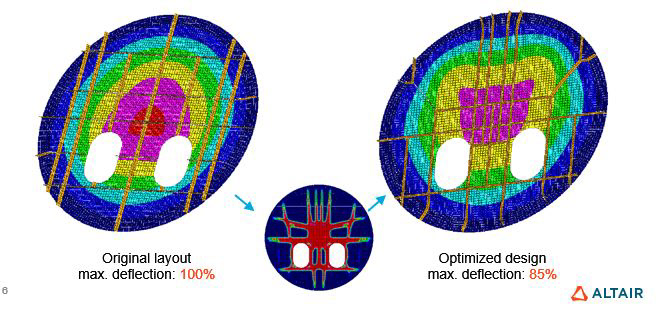
The existing documentation on this topic is more of an example: in three slides, they explain the original part and end up with an optimized part, clearly demonstrating the potential of the feature, but not going in-depth on how and where the feature can be utilized.
It was also made in 1998 or so, and is older than me! The original files that accompanied the presentation are no longer openable, so I had to start from scratch and generate all models that would be used in the demonstration.
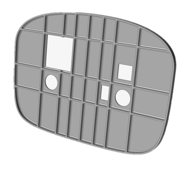
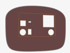
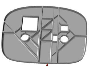
The first thing I did was create this bulkhead that the tutorial would be based on. I created it in Solidworks, and it is loosely based on the bulkhead of a mid-sized plane. It is simplified a bit, but gets the point across.
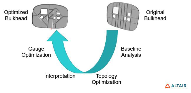
Next, through some experimentation, I came up with this workflow that would allow an engineer or designer to optimize their part.
Starting with their original part, they analyze it to get a baseline point of comparison. Then they perform a topology optimization, locating the best position for ribs within the bulkhead. After interpreting the many optimization results, they move onto gauge optimization, in which the many ribs or groups of ribs are sized (setting thickness) to ensure that all mass is being utilized as effectively as possible.
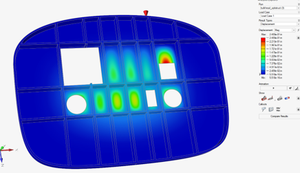

This is the baseline analysis step. In this part, the weight is 122 lbs, and the maximum deflection under load is .25in.

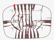
Next, my tutorial has users run several optimizations and walks them through setting up each one.
Here I've pictured the original model (top left), which is a mid-surfaced version of the original part (with ribs removed). The two patterns next to it are maximize stiffness runs, while the two under them are minimize mass runs.
By taking all these patterns into account, one decides on an optimal pattern and move on to the next step.

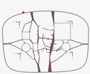
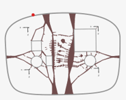
After selecting a pattern, another bulkhead is made, and gauge analysis is run to set the thickness of each rib. With this final optimization run, I set up another analysis to compare to the original.
After all the optimizations, the part weighs 100lbs and deflects .1in under load. this represents an 18% reduction in mass and a 60% reduction in max deflection.
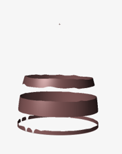
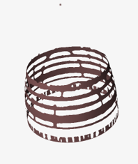
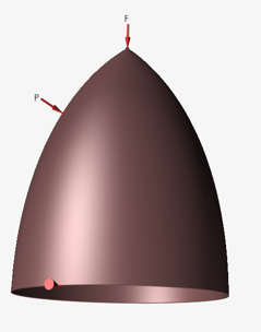
Applications to conical models (Northrop Grumman asked about this)